Roberts of Ruabon

IMG_0015

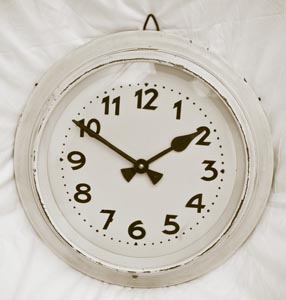
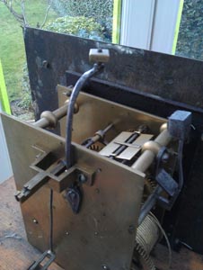
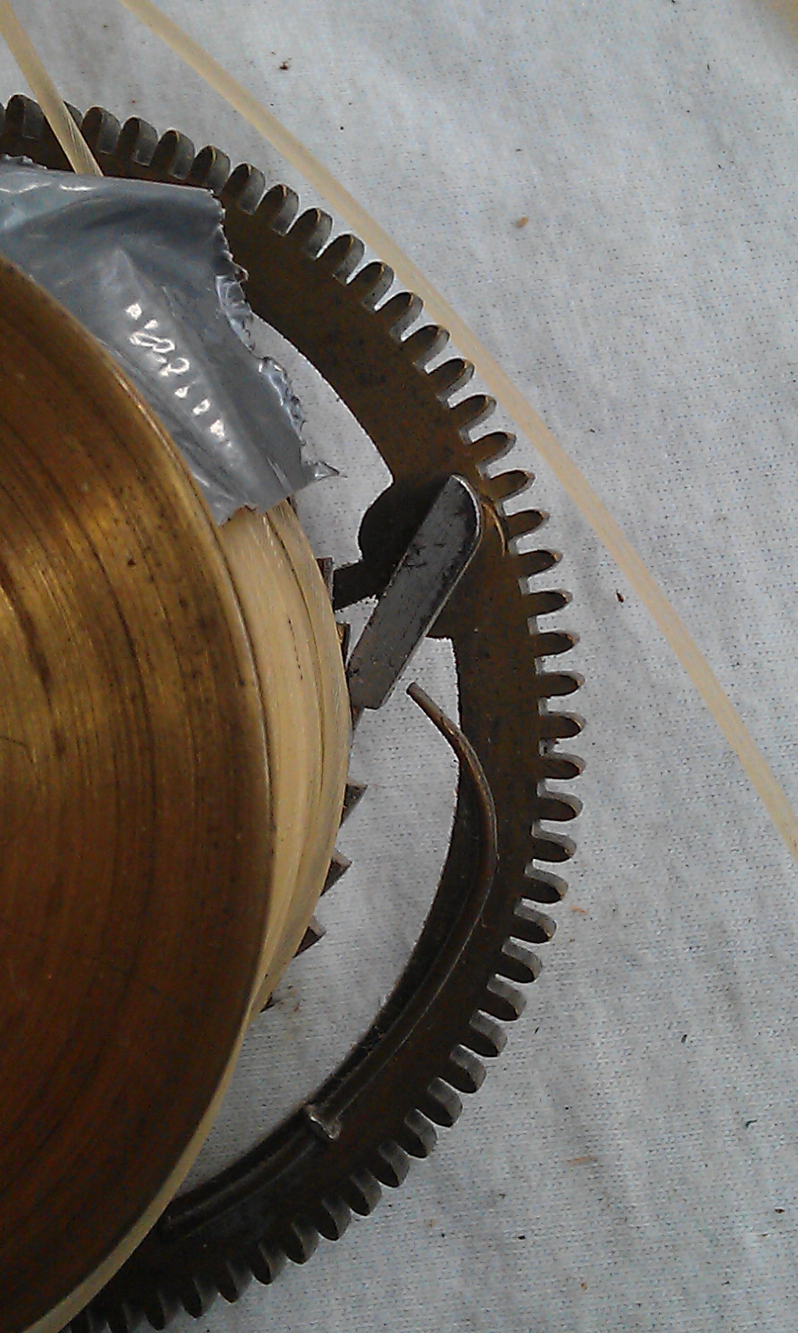
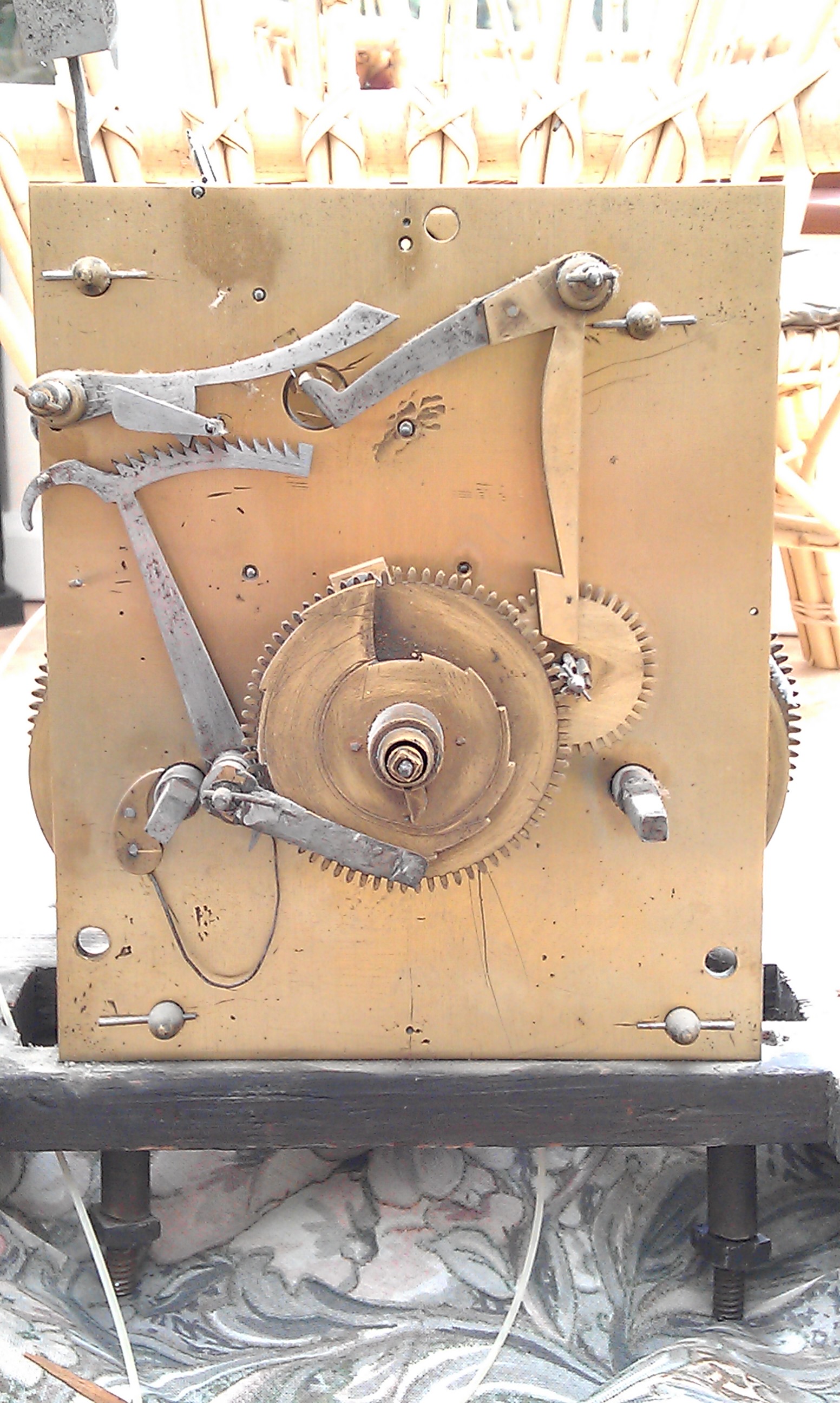
I was called to look at a long case clock that was having problems. The case was very shallow and I could see where the weights had been touching the inside of the front of the case, but moving the movement a fraction backwards caused the pendulum to rub on the backboard. The brass dial is inscribed with Jon Roberts Ruabon, who was active there until 1759 when he apparently moved to Wrexham. The owner kindly delivered the movement to me and I’ve been able to have a better look at the clock on the workshop stand. It’s revealed a bit of a puzzle. The clock runs for a while then simply stops, but the escapement (escape wheel/pallets combination) is not working correctly as it appears that either the escape wheel is on back-to-front or the pallets are incorrect – possibly due to a repair in the distant past. I’ve shot a brief video that shows the operation; it’s on youtube at:

http://www.youtube.com/watch?v=wkO0iO5QC1M

I’ve linked this video to an internet horology discussion group to try to sort out the best way to correct this whilst maintaining the integrity of the clock. There are also a couple of other things that have become apparent – the great wheel on the strike side is loose on the barrel arbor, the click spring on the going barrel needs to be replaced, and the rack hook spring is far too weak.

IMAG0609   IMAG0600

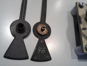
Dismantling the clock unfortunately revealed further wear and tear and more puzzles. The brass dial is attached to a false plate which suggests it is not original to the movement, but the false plate seems to be riveted onto the dial with very old rivets! There is also evidence of alterations to the false plate, namely pencil marks showing where additional cutouts were needed:

IMG_0013

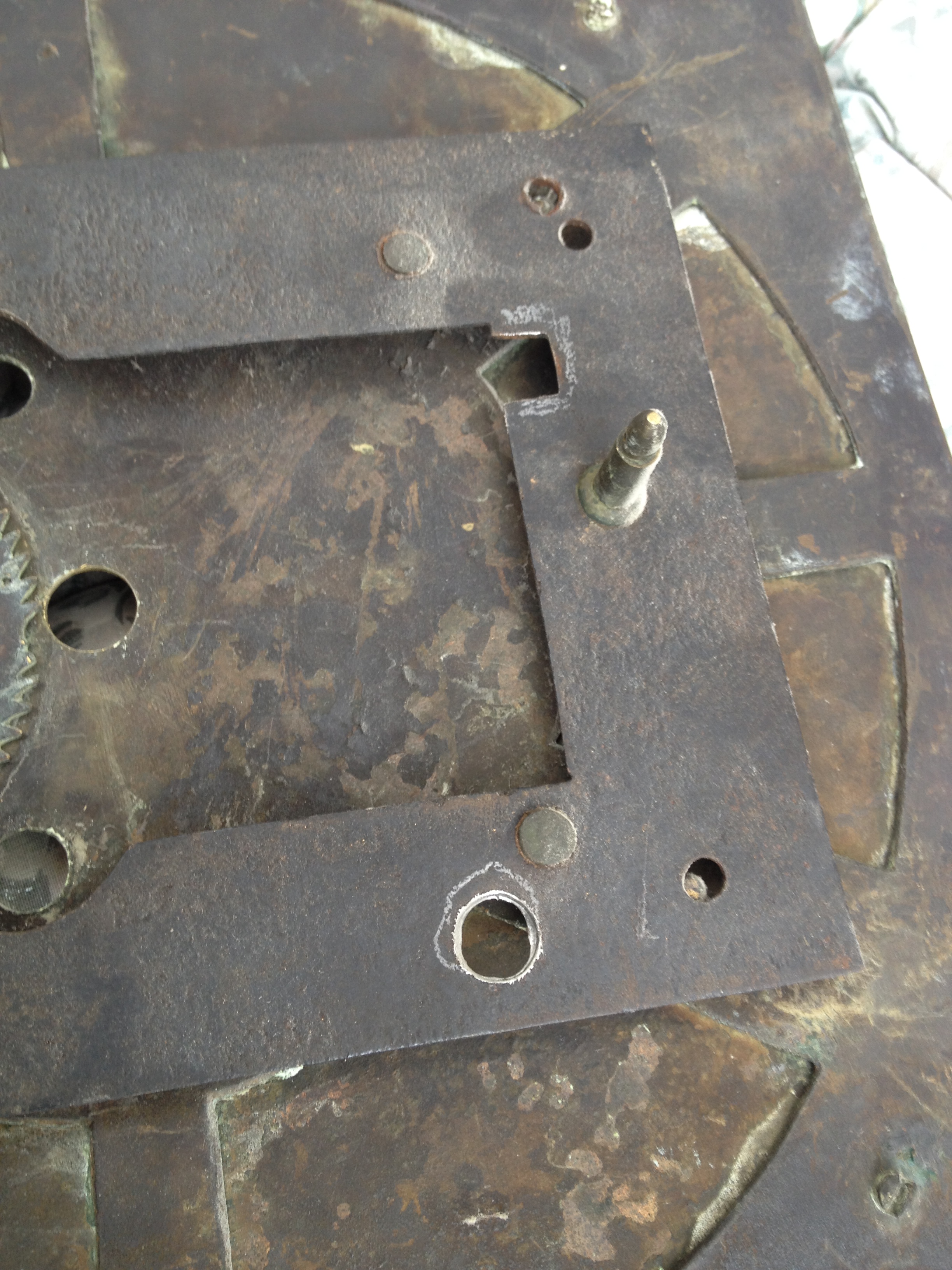
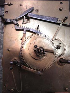
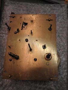
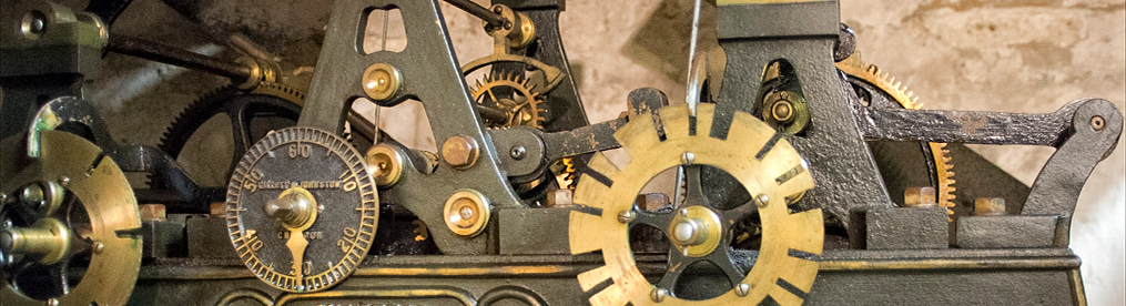
Many of the pivot holes in the plates had been hammered with a centre punch in an attempt to close them to compensate for pivot wear:

IMAG0610 IMAG0612 IMAG0613 IMAG0614

But in most cases this seems to have had the effect of creating a sharp edge to the pivot hole which has helped to wear the pivots badly:

P1050038 P1050041 P1050042

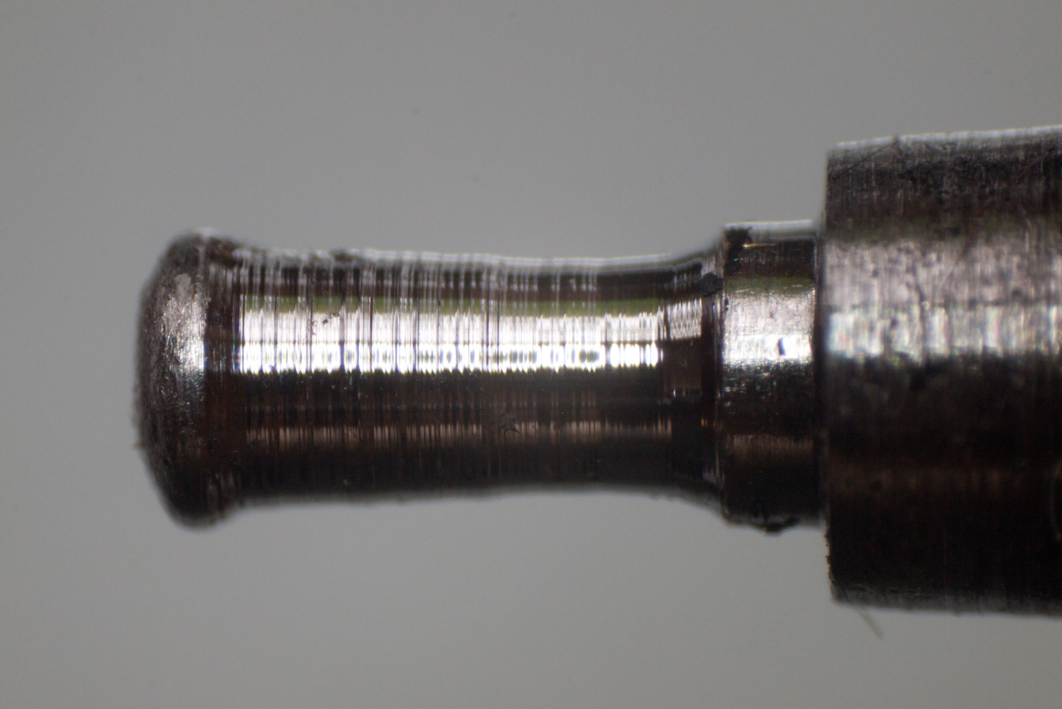
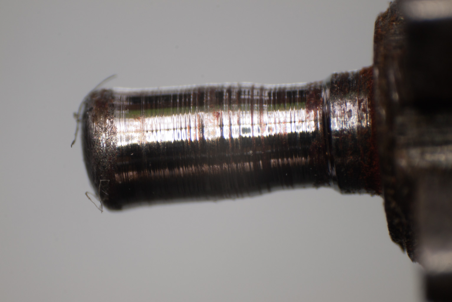
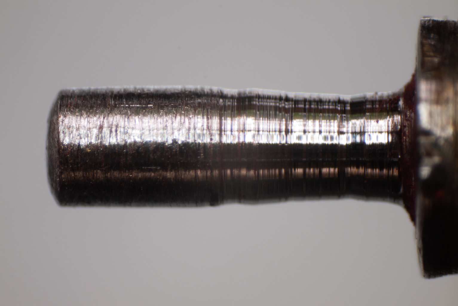
Careful measurement leads me to believe that there is just enough metal remaining to turn down the pivots rather than have to re-pivot entirely. The affected pivot holes will of course have to be bushed.

Quartz conversion 2a

I received a call from the owner of one of my recent slave-clock quartz conversions, that it was running slow and occasionally stopped!

DSC_4552  IMAG0303


Back in the workshop I noticed that the counter-weight portion of the hands were extremely close at certain positions, and my guess is that they had been touching. The hands had small additional weights riveted to them which increased their thickness, so since I used a high torque movement I removed the weights and the clock has been running fine for several days.

John Tucker of Tiverton – part 5

Progress on the clock is slow but steady. Last time I mentioned that I had posted a question to the NAWCC discussion forum regarding the repair/replace question for the going-train great wheel. There have been an amazing 63 replies, with opinions ranging from “repair-and-conserve-at-any-cost” to “definitely-replace-on-safety-grounds.” You can read the discussion here:

http://mb.nawcc.org/showthread.php?99050-Advice-please-on-long-case-great-wheel-repair

My view has not changed, I am going to make a new wheel, largely on safety grounds, but hope to attempt a repair on the old one later. So last week the new wheel blank was blued, marked out, mounted on an arbor, turned to size, and then mounted on the wheel cutting engine to have the 96 teeth cut.

IMAG0365

Calculations suggested a cutter of 0.85M for a wheel of this size (84mm diameter) and 96 teeth, but the slightly smaller 0.80M was a better fit between the teeth of the old wheel – 0.85M was a tight fit and I was concerned that the teeth may be cut too thin.

IMAG0367

The wheel with all 96 teeth cut. It took 1 hr 20 mins to carefully cut all the teeth with slow hand feed. I will bore and broach the barrel arbor hole next before cutting the crossings.

John Tucker of Tiverton – part 4

I have been a little concerned about the condition of the great wheel on the going train barrel. This wheel had broken at some time in the past and had been soft-soldered together. As I was bushing the central arbor hole it became obvious that the wheel was not flat, nor was it truly circular.

DSC_0992    DSC_0994

This wheel is subject to great stress as it carries the weight hanging from its barrel. I consulted with my colleagues at EFHC and I also posted a query to the NAWCC discussion forum regarding the best way to repair this wheel. The almost unanimous view was that it would be too risky to try a repair, and for safety’s sake a new wheel  should be cut. I’ve now cut a wheel blank from 1/8 in CZ120 brass and I’ll shortly be marking out the wheel and cutting the teeth. I will make the spokes a little wider for strength, and I will also add a thicker portion where the click will be attached.

John Tucker of Tiverton – part 3

Parts 1 and 2 of this series looked at the faults found in a c1785 long case clock movement. Now I start on the repair.

Before any work could be done on the bushes in the plates I needed to repair the barrels and great wheels. Here is the strike barrel great wheel mounted in a six-jaw chuck on a Schaublin lathe.

IMAG0349IMAG0347

It’s been bored out true, a brass rod has been turned to a press fit into the hole to form a bush, and the bush is being skimmed back to the wheel thickness prior to centering, drilling and broaching the correct size hole for the barrel arbor.

John Tucker of Tiverton – part 2

In part 1 I started to look at a long case clock with a broken click spring on the strike barrel. Here I dismantle the clock and find a number of faults that need to be attended to!

IMAG0325IMAG0337

The first view above shows the mechanism with hands, dial and false plate removed, the second with the strike parts removed, together with the bridge and motion work. We can start to see some of the clock’s history now! Most, if not all, of the parts of the clock have been repaired at some stage. Every one (yes, every one!) of the pivot holes in both front and rear plates has been bushed, and nearly all are worn to the stage where they require to be renewed.

DSC_4557_3DSC_4557_4DSC_4558_1DSC_4557_1

The plates have been extensively hammered to try to close the holes, and even the winding arbor bushes, “top-hat” style, have been struck.

DSC_4561IMAG0338

The great wheel on the strike barrel (above left) is not original, and the great wheel on the going barrel (above right) has been extensively repaired, having been broken into three pieces at some stage. Note the big difference in length of teeth between the two wheels. In both cases there was too much clearance at the wheel centre on the arbor, and this is affecting the depthing with the next pinion. The domed brass retaining washers which hold the great wheels to the barrel but allow it to turn (shown above right) had lost most of their spring and were ineffective.

Here are close-ups of the repairs to the going train great wheel; note the inserted tooth, and the misalignment of the rim!

DSC_4567DSC_4566

Here are further photos of parts of the mechanism that have been repaired at some time in the past.

DSC_4570DSC_4569DSC_4568DSC_4565

John Tucker of Tiverton – part 1

A telephone caller asked if I could look at a long case clock. When winding it the strike mechanism weight had fallen to the bottom of the case.

I suspected a broken gut or chain, but when I had a look at the clock the gut was intact. However, the click spring on the strike barrel appeared to have broken and was no longer holding the click in place – that would explain why the weight had fallen. I initially hoped to be able to replace the click spring without taking the clock away, but there was limited clearance between the great wheel, barrel and a pillar and I couldn’t reach it properly. So hood, weights and pendulum were taken off, and the mechanism was free to lift out.

IMAG0318P1040776

The first view above is the mechanism from the rear, the second is the dial with the hands removed. It’s very soon apparent that the clock is a marriage of dial and mechanism; between the front clock plate and the dial is a cast iron false plate, normally associated with painted dials, whereas this dial is brass. A closer view shows how the brass dial has been modified to fit the mechanism; the winding holes and date slot have been cut through the maker’s name, and under the “r” of Tiverton can be seen the pivot for the date wheel.

P1040777

The next view is of the false plate from the mechanism side.

P1040774P1040775

A close-up of one corner shows that the false plate is broken into several pieces and has been plated and riveted. My guess would be that the clock has fallen over at some time and the original painted dial was smashed. The false plate was repaired and a brass dial was modified to fit. A quick search of the literature suggested that several features of the mechanism would date the clock to around 1785, so I guess it’s showing its age and history.

Quartz conversion 2

Soon after converting the Brillie clock (link here) another european slave clock was brought in.

DSC_4552


This one has no maker’s name, is about 15ins across, and the only markings are the numbers “46” on the slave mechanism and on the hands, and a hint of a “cross” on the number 7 on the dial.

IMAG0300            IMAG0303


Once again a UTS high torque quartz movement was used, and again the hands needed some careful broaching and a euroshaft collet. A round access hole was cut in the rear of the case to allow the hands to be moved and batteries replaced without dismantling the clock.

Quartz conversion 1

IMAG0308

Brought in recently, a large (12in glass) school or factory slave electric clock. These clocks work on pulses sent every minute or half minute from a master clock. This one is French, with the maker’s name, Brillie, painted on the dial.

IMAG0314

The mechanism as fitted cannot be directly converted to battery or mains operation, and although there are add-on units which retain the pulse mechanism it is easier to install a quartz movement. I used a UTS high torque movement to cope with the large hands which the client wanted to retain. The hour hand was broached out to be a nice push fit on the Euroshaft spindle, but the minute hand needed a hand collet soldered to the underside.

The mounting of the glass in the bezel also needed attention as the original plaster sealing had dried to a powder – transparent silicone did the job. The dial and mechanism is retained by screws in a substantial spun aluminium case, and the final task was to cut a round access hole in the rear so that hands can be adjusted and batteries replaced without dismantling the clock.